Select your product to confirm this information applies to you
TüN® 4 and MAX™: Error Messages in TüN® Software
TüN® Software is a very powerful measurement system as well as a JL Audio DSP controller. When taking measurements with TüN®, there is a chance that a user may experience information dialogs and or error messages during the tuning process. This article discusses common messages and dialogs, and what may cause them.
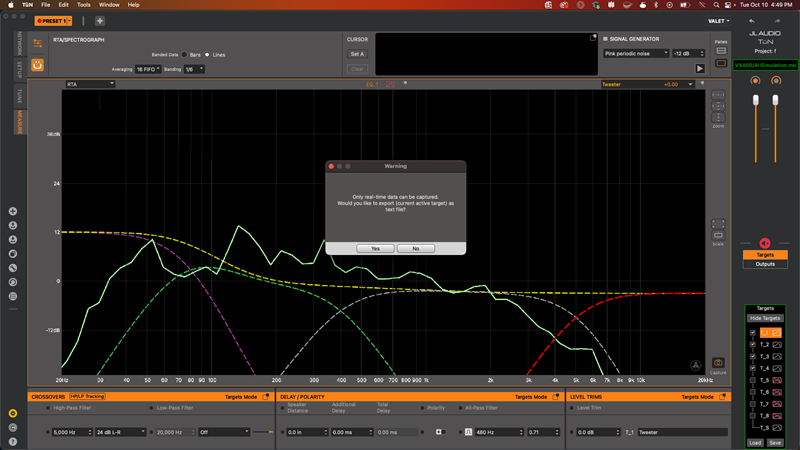
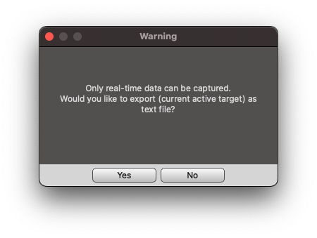
Figure A - Image shows information dialog box when capturing data
Figure A displays one of the most common messages that a user may experience. This usually happens when a user is trying to capture a measurement on the graph. The ‘Z’ order determines the front to back order of traces displayed within the graph window. The measurement that is being captured needs to be on the top layer of the graph. There are two ways to toggle the 'Z' order within the graph window.
- The user can click on the Input Combo Box (top right corner of the graph window) downward pointing arrow and select the desired active measurement data from the list
- The user can press the Z key on the keyboard until the desired active measurement data moves to the front of the graph window
Figure A currently displays ‘Tweeter’ in the Input Combo Box. This means that the Tweeter Target is on the top layer of the graph window, which is also thicker than the other traces by default (the thickness of traces can be manually adjusted for preference within the MEASURE Settings). The active Cursor and the data in the Information Display will be the same color as the selected input. If the user wishes to export the data as a .TXT file, select ‘Yes’.
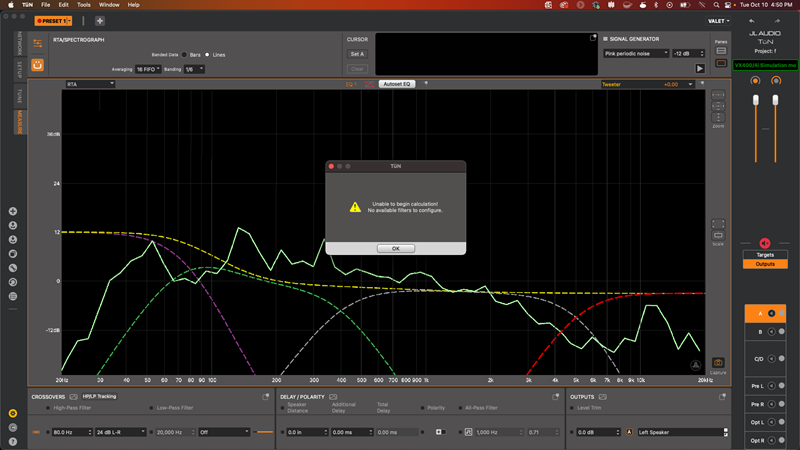
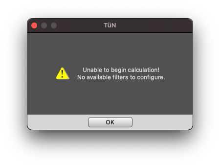
Figure B - Image shows error message when using Autoset EQ
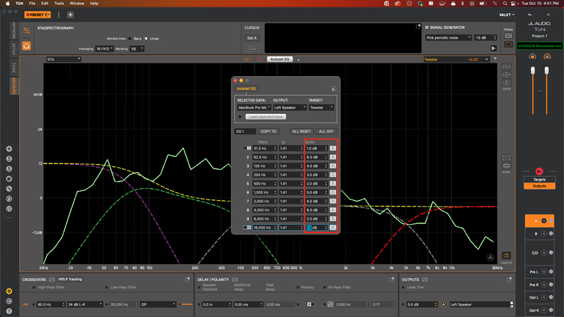
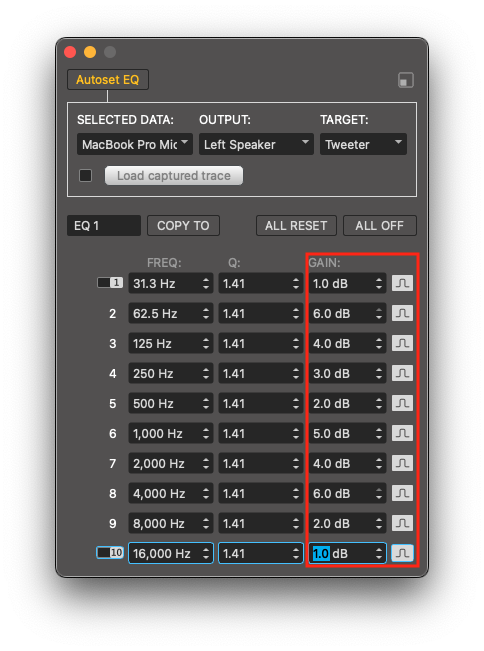
Figure C - Image shows EQ Panel with all EQ bands in use
Figure B displays another common message that a user may encounter. This usually occurs when all of the EQ bands for that channel have already been used, or have been toggled off. As an example, Figure C displays a gain value applied for all EQ bands. If all EQ bands have a gain value applied (negative or positive), TüN® will determine that no more EQ bands are available, therefore it cannot begin the Autoset EQ process. The user can either choose to reset some, or all of the EQ bands to use the Autoset EQ feature and/or perform manual adjustments.
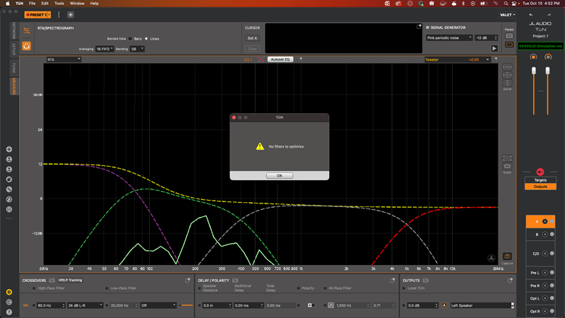
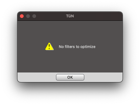
Figure D - Image shows error message when using Autoset EQ
Figure D displays a message that usually occurs when using the Autoset EQ feature. TüN® will not attempt to equalize a measured response that is improperly aligned (visually) with the desired target trace within the graph window. Based on the position of the data relative to the desired target, and the banding (resolution of the data) applied, there is nothing that the Autoset EQ feature will attempt to correct. If the user has a desired result, manual adjustments can be made to equalize the measured response. If no equalization has been applied, repositioning the measured data slightly above the target trace (visually) may result in a functional Autoset EQ operation. Ensuring that the data is touching the slope of the desired target before using equalization (Autoset EQ/manual EQ) is good practice.
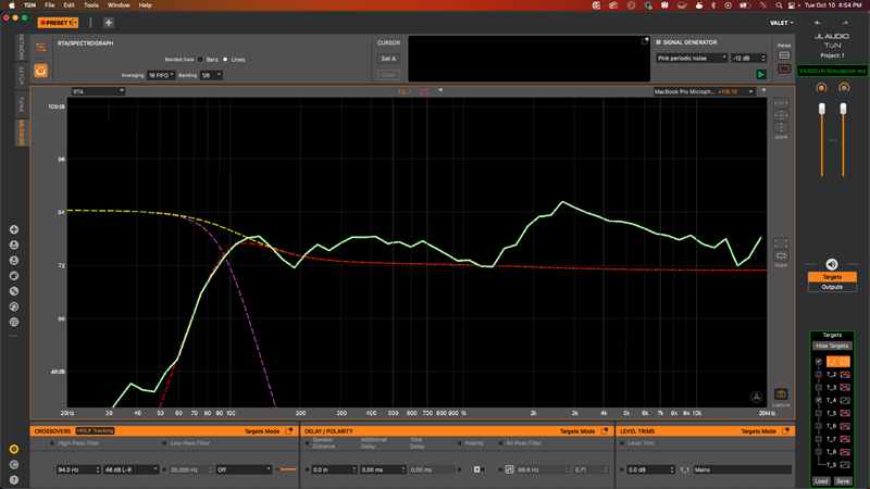
Figure E - Image shows data touching the slope of the Midrange Target
Figure E displays measured data that is appropriately aligned with the desired target trace and slope in the graph window.
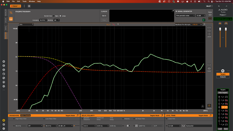
Figure F - Image shows data not touching the slope of the Midrange Target
Figure F displays measured data that is appropriately aligned with the desired target trace but not aligned with the target slope in the graph window. Note: Read TüN® 4: Autoset EQ to Target for further assistance with the Autoset EQ Feature.
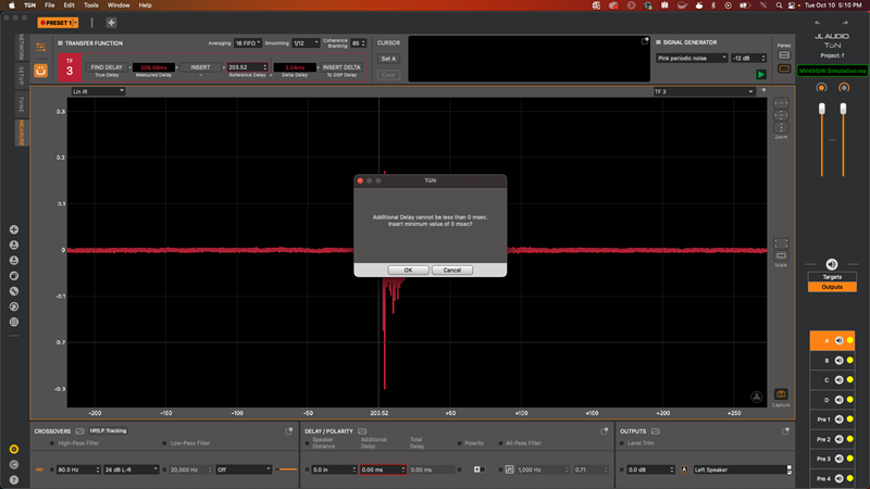
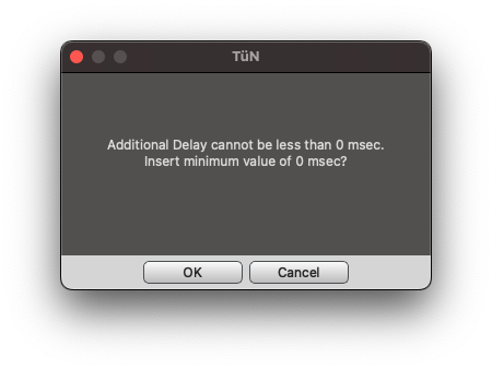
Figure G - Image shows error message when using the True Delay Finder
Figure G displays a message when using the True Delay Finder with the MAX™ Audio Measurement System. When the ‘Find Delay’ button is pressed, TüN® will attempt to find the beginning of the Impulse Response of the active measurement data, then display that value in the Measured Delay field. If this is the latest arriving signal in the system, then the ‘Insert’ button should be pressed. If the ‘Insert Delta’ button is pressed instead, then this error message will appear. This is due to the measured signal arriving later than the Reference Delay, therefore no delay can be applied. Sometimes this will happen if there is no Impulse Response visible causing the value displayed in the Measured Delay field to be an excessively large value (exceeded time limit). If an Impulse Response is not visible, the True Delay Finder will not function appropriately.
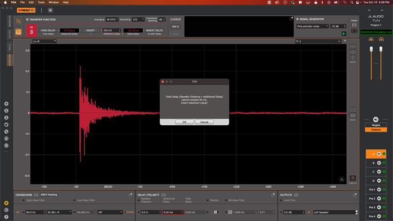
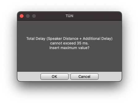
Figure H - Image shows error message when using the True Delay Finder
Figure H displays a message that refers to the maximum delay capability of a connected device. JL Audio DSP products' maximum delay capabilities vary. As an example, an MVi DSP amplifier is connected in Figure H, which has a maximum delay capability of approximately 35 mS. When using the True Delay Finder to measure signals, the measurements (whether suitable or not) could exceed the limitation of the connected device. In this instance, the value in the Delta Delay field exceeds 35 mS. When the ‘Insert Delta’ button was pressed, TüN® displayed this error message. This error will show up every time the value attempting to be added with the True Delay Finder is higher than the digital signal processor's maximum delay capability. Note: Read TüN® 4 & MAX™: Using the True Delay Finder for further assistance.